Wireless Battery Charger
Wireless Battery Charger Wireless Battery Charger :

This circuit mainly works on the principle of mutual inductance. Power is transferred from transmitter to the receiver wirelessly based on the principle of “inductive coupling”.
Inductance is the property of the conductor, in which the current flowing in a conductor induces a voltage or electromotive force in it or in another nearby conductor. There are two types inductance. 1) Self inductance, 2)Mutual Inductance.
“Mutual inductance” is the phenomena in which, when a current carrying conductor is placed near another conductor voltage is induced in that conductor. This is because, as the current is flowing in the conductor, a magnetic flux is induced in it. This induced magnetic flux links with another conductor and this flux induces voltage in the second conductor. Thus two conductors are said to be inductively coupled.
Wireless Power Transfer Circuit Diagram:
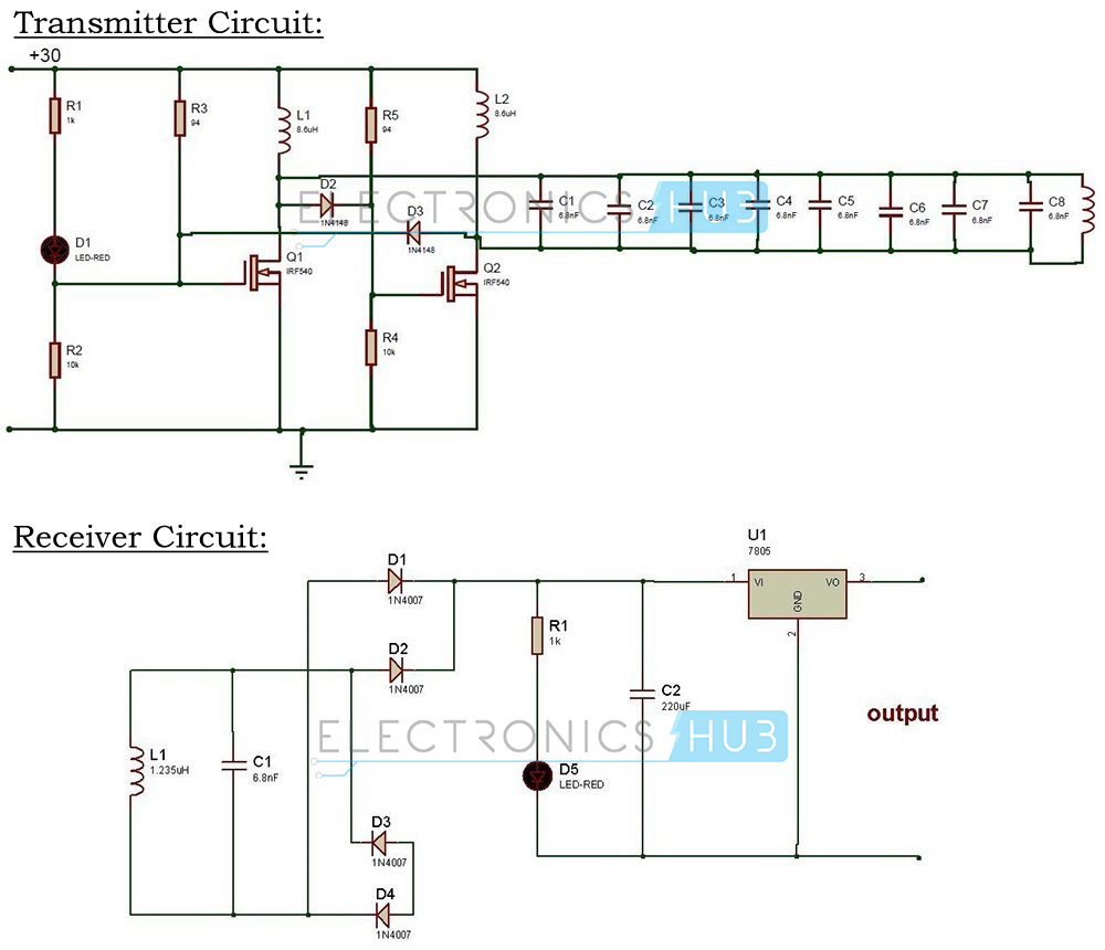
Wireless Mobile Charger Circuit Diagram
Wireless Mobile Charger Circuit Design:
Wireless battery charger circuit design is very simple and easy. These circuits require only resistors, capacitors, diodes, Voltage regulator, copper coils and Transformer.
In our Wireless battery charger, we use two circuits. The first circuit is transmitter circuit used to produce voltage wirelessly. The transmitter circuit consists of DC source, oscillator circuit and a transmitter coil. oscillator circuit consists of two n channel MOSFETS IRF 540 , 4148 diodes. When the DC power is given to the oscillator, current starts flowing through the two coils L1, L2 and drain terminal of the transistor. At the same time some voltage is appeared at the gate terminals of the transistors. One of the transistors is in on state while the other is in off state. Thus voltage at drain of transistor which is in off state raises and it fall through the tank circuit made of 6.8nf capacitors and transmitter coil of 0.674. Thus operating frequency is determined by using formula F=1/[2π√(LC)].
In the second circuit that is receiver circuit consists of receiver coil, rectifier circuit and regulator. When the receiver coil is placed at a distance near the inductor Ac power is induced in the coil. This is rectified by the rectifier circuit and is regulated to DC 5v using 7805 regulator. The rectifier circuit consists of 1n4007 diode and capacitor of 6.8nf. The output of regulator is connected to the battery.
NOTE: Also get an idea about the Battery Level Indicator Project Circuit and its Working
How to operate this Wireless Power Transfer Circuit?
- Initially, connect the circuit as shown in the circuit diagram.
- Switch on the supply.
- Connect the battery charger at the output of the circuit.
- Place the receiver coil near the transmitter coil .
- You can observe the charging of battery.
Wireless Battery Charger Circuit Advantages:
- Usage of separate charger is eliminated.
- Phone can be charged anywhere and anytime.
- It does not require wire for charging.
- Easier than plug into power cable.
Wireless Power Transfer Circuit Applications:
- Wireless chargers can be used to charge mobiles, camera batteries, Bluetooth headsets etc.
- This can also be used in applications like car battery charger with little modification. Go to Simple Car Battery Charger Circuit post for more information.
- This can also be used in medical devices.
Limitations of the Circuit:
- Power is somewhat wasted due to mutual induction.
- It will work for very short distances only. If you want to use it for long distances, then the number of inductor turns should be high.
In the future all electronic devices will be wirelessly powered. Small, battery-powered gadgets make powerful computing portable.
The battery charger should be capable of charging the most common battery types found in portable devices today. In addition, the charging should be controlled from the base station and a bidirectional communication system between the pickups and base station should be developed.
Inductive Power Systems:
Inductive Power Transfer (IPT) refers to the concept of transferring electrical power between two isolated circuits across an air gap. While based on the work and concepts developed by pioneers such as Faraday and Ampere, it is only recently that IPT has been developed into working systems.
Essentially, an IPT system can be divided into two parts;
- Primary and
- Secondary.
The primary side of the system is made up of a resonant power supply and a coil. This power supply produces a high frequency sinusoidal current in the coil. The secondary side (or ‘pickup’) has a smaller coil, and a converter to produce a DC voltage.

Working of Inductive Power Transfer:
In this system communications signals are encoded onto the waveform that provides power to the air gap. Communication from the primary side to the secondary is implemented by switching the power signal at the output of the resonant converter between its normal level and a lower level which is detectable by the pickup but still provides enough power to control the pickup microcontroller. This process is called Amplitude Shift Keying (ASK). This is achieved by varying the output voltage of the buck converter which provides an input DC voltage to the resonant converter.

Communication from the secondary to the primary is achieved by a process called Load Shift Keying (LSK). This involves varying the loading on the pickup. Any load on the pickup will reflect a voltage on the primary circuit proportional to the load. Therefore a variation in the load on the pickup can be detected by the charging station.
The communications system must provide two discrete levels of voltage reflected onto the primary side, to represent the on and off states for digital communications. The difference must be easily detected on the primary side to provide a robust communications channel. Signals are decoded by simple filters and comparators which feed a digital signal to the microcontrollers.
Advantages:

IPT has a number of advantages over other power transfer methods – it is unaffected by dirt, dust, water, or chemicals. In situations such as coal mining IPT prevents sparks and other hazards. As the coupling is magnetic, there is no risk of electrocution even when used in high power systems. This makes IPT very suitable for transport systems where vehicles follow a fixed track, such as in factory materials handling.


